

Introduction
Each Boolean function, such as the logic AND function, typically has one or more input values and produces an output result based on these inputs. The inputs have two possible values: 0 or 1.


Symbol of AND Gate
The AND gate is a fundamental digital logic gate that implements the logical conjunction from mathematical logic. A HIGH output (1) is produced only if all of the AND gate’s inputs are HIGH (1). If even one input is LOW (0), the output becomes LOW. The AND function can take any number of inputs. Many integrated circuits operate on this logic. Let us first understand how an AND Gate output behaves in relation to its inputs.
The binary numbers are 0 and 1. We’ve already established that an AND gate performs binary multiplication of binary digits:
- 0 × 0 = 0
- 1 × 0 = 0
- 1 × 1 = 1
In other words, an AND gate is a digital device that produces a HIGH output when all inputs are HIGH and a LOW output when any input is LOW. A high digital signal denotes a logical 1 and a low signal denotes a logical 0.
An AND gate can have multiple input terminals but only one output terminal.
The theory of Boolean Algebra is based on the concept that logic and set operations can be either “TRUE” or “FALSE,” but not both at the same time. For example, A + A = A, not 2A as in standard algebra.
Boolean Algebra provides a simple and effective way to represent the switching action of standard logic gates. The basic logical statements are represented through AND, OR, and NOT gate operations.
The Logic AND Function
The Logic AND function specifies that two or more events must occur simultaneously for an output action to happen. The order of occurrence does not affect the result, as it follows the Commutative Law of Boolean Algebra, where A · B = B · A.
In electronics, the AND function is represented by the dot symbol (·). For example, a 2-input AND gate with inputs A and B has an output represented by the Boolean expression A · B or simply AB.
AND Gate Circuit Example
Consider a simple series circuit with two switches, A and B, connected to a lamp. Both switches must be closed (Logic “1”) for the lamp to turn ON. If either switch is open (Logic “0”), the lamp remains OFF.
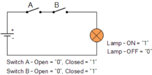
This demonstrates that an AND gate produces an output only when all inputs are active (Logic “1”). In Boolean Algebra, the output is TRUE only if all inputs are TRUE.
Truth Table of AND Function
| Input A | Input B | Output (A · B) |
|---|---|---|
| 0 | 0 | 0 |
| 0 | 1 | 0 |
| 1 | 0 | 0 |
| 1 | 1 | 1 |
AND Gate IC Packages
Standard integrated circuit packages for logic AND gates include:
- TTL 74LS08 – Quadruple 2-input positive AND gates (or 4081 CMOS equivalent)
- TTL 74LS11 – Triple 3-input positive AND gates
- TTL 74LS21 – Dual 4-input positive AND gates
AND gates can also be cascaded to form circuits with more than four inputs, allowing for complex logic operations.
Conclusion
The logic AND gate is one of the most essential components in digital electronics. It forms the foundation of many logical operations and decision-making circuits. Understanding its function, truth table, and Boolean representation is crucial for anyone studying or working in electronics or digital system design.


