

Introduction
An LCR meter is an electronic test instrument used to measure an electronic component’s inductance (L), capacitance (C), and resistance (R). Earlier versions measured impedance internally and converted it to the corresponding capacitance or inductance value for display.
If the capacitor or inductor under test does not have a significant resistive component, readings are generally accurate. Modern LCR meters measure true inductance or capacitance, capacitor equivalent series resistance (ESR), and the Q factor.

LCR Meter Basics
An LCR meter is typically built around two main measurement techniques:
1. Bridge Method
This method operates on the well-known Wheatstone bridge principle. The goal is to balance the bridge so that no current flows through the detector. The component’s value is then determined from the bridge balance point. This method is mostly used for low-frequency measurements, up to around 100 kHz.
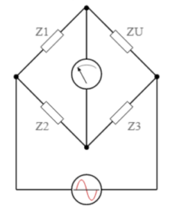
The DUT (device under test) is placed in the bridge circuit, and its value is determined by adjusting the other known impedances. LCR meters using this technique are often referred to as LCR bridges.
In older LCR meters, this circuit had to be balanced manually. Modern instruments automate the balancing using integrated circuits and operational amplifiers.
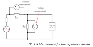
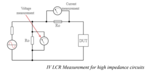
2. Current–Voltage (I–V) Measurement Method
This technique is used for high-frequency applications and offers highly accurate measurements. It uses voltage and current measurements along with impedance-matched circuits. For very high frequencies, precision coaxial test ports may be used.
Two arrangements are commonly used—one for low-impedance and one for high-impedance DUTs. The impedance of the DUT is calculated from the measured voltage and current. The phase difference between voltage and current helps determine the resistive, capacitive, and inductive properties of the DUT.
A transformer may be used for isolation, but it can limit the frequency range.
Types of LCR Meters
1. Handheld LCR Meters
These portable, battery-powered meters are ideal for field use and general testing. They often include a USB interface for computer connectivity. Handheld LCR meters typically measure AC resistance and inductance with an accuracy of 0.1% to 0.2%.
Common test frequencies include 100 Hz, 120 Hz, 1 kHz, 10 kHz, and 100 kHz. The measurement range and resolution vary depending on the applied test frequency.
2. Benchtop LCR Meters
These are used mainly for calibration of resistors, capacitors, and inductors. They support multiple test frequencies such as 100 Hz, 120 Hz, 1 kHz, and 10 kHz, along with additional features like programmable frequency, high accuracy, DC bias voltage/current, sweep functions, etc.
High-end benchtop models may offer frequencies above 100 kHz, and some support DC superposition internally. They also support fixtures for measuring transformers, air-core coils, and SMD components.
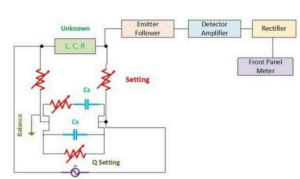
Block Diagram
The LCR meter uses a DC source for DC measurements and an AC oscillator (typically at 1 kHz) for AC measurements. The bridge network is excited accordingly depending on whether DC or AC parameters are being measured.
Working of an LCR Meter
The DUT is typically excited with an AC voltage source. The meter measures the voltage across and the current through the DUT. Using their ratio, the instrument computes impedance. Advanced meters also measure phase angle to calculate equivalent R, L, or C values.
Real-world components are not ideal. Capacitors have some inductance and resistance; inductors have some resistance and capacitance; even resistors can exhibit inductance and capacitance. Therefore, LCR meters use series or parallel models depending on the component type.
LCR meters are also used in permanent magnet machines to measure inductance variation with rotor position. However, turning the rotor may induce EMF, which can damage some meters.
High-end meters offer selectable test frequencies (100 Hz, 120 Hz, 1 kHz, 10 kHz, and 100 kHz or more). Benchtop devices may include Kelvin connections for high-precision low-impedance measurements.
Advantages
- Handheld meters are portable, lightweight, and battery-powered.
- Benchtop meters offer higher accuracy and more advanced features such as programmable frequencies, DC bias, and sweep capability.
- No voltage-related issues during normal operation.
- High-quality measurements with excellent accuracy.
- Compact, easy to use, and suitable for various applications.
Disadvantages
- They measure only passive components.
- The LCD display depends on battery power in handheld models.
- Excess voltage input can damage the meter.
Applications
- Used to measure resistance, capacitance, and inductance at various frequencies.
- Widely used to determine impedance (Z) of components and circuits.
- Commonly used by electrical engineers, manufacturers, and maintenance professionals.


