
Product designers may assume a high shock rating means a MEMS accelerometer is rugged enough for harsh environments, but shock and vibration stress the device in different ways. A single shock event tests whether the sensor can survive a peak acceleration, while sustained vibration can limit its ability to keep operating accurately over repeated stress cycles.
A g-shock rating identifies the peak acceleration a MEMS sensor can survive, but it does not fully predict behavior in real operating environments. A device with a high shock survivability rating may still be vulnerable to lower-magnitude repetitive vibration if its mechanical design lacks sufficient damping or headroom. Designers who evaluate both single-event shock survivability and repeated vibration performance are less likely to encounter premature failures or degraded performance in the field.

Vibration performance is governed by how much mechanical headroom remains under continuous, frequency-dependent excitation, while shock performance is defined by how much peak acceleration the device can survive in a single event. However, neither fully describes how rapidly that shock is applied. This is where the rate of change of acceleration becomes relevant, capturing the difference between a slow-building impact and an extremely abrupt one that can stress the MEMS structure in fundamentally different ways, even at the same peak g level.
The rate-of-change specification becomes important when acceleration rises rapidly, as in automotive crash detection, airbag deployment, ballistics and munitions, and industrial impact monitoring. Simply put, two shocks with the same peak g can produce very different mechanical stresses if their rise times differ. In other words, surviving a high peak acceleration is not necessarily the same as surviving a very fast acceleration.
That distinction matters because qualification tests do not all measure the same kind of mechanical stress. Some tests focus on sustained vibration, others on sudden shock, and still others on post-event performance. Specific international testing standards provide designers with a starting point for how to select components that balance immediate survival with sustained operational performance:
- MIL-STD-883 Method 2007 specifies testing to determine whether a microcircuit can withstand sinusoidal vibration across a wide frequency range without suffering mechanical damage or degraded performance during transportation and operation.
- IEC 60068-2-27 extends the testing concept to electronic components, assemblies, and complete products. It establishes standardized mechanical shock tests to ensure that equipment can endure sudden impacts that might cause beam breakage, wire bond detachment, or die cracking during shipping, handling, or operation.
Analog Devices, Inc. (ADI) and other suppliers complement these standardized qualifications with additional insight into how the sensor will perform in applications where shock events occur with exceptionally rapid rise times. Designers may have to evaluate different vendors’ specifications of combinations of peak acceleration, pulse duration, frequency range, and post-test performance criteria.
First line of defense
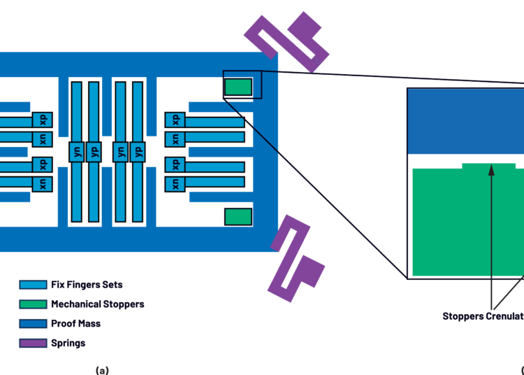
The ability to withstand shock and vibration ultimately hinges on the MEMS sensor’s internal mechanical design. At the core of every accelerometer is a microscopic proof mass suspended by delicate flexures. During normal operation, the proof mass moves only slightly in response to acceleration. During severe shock or vibration, however, its motion can become large enough to damage the sensing structure unless protective features are built into the device.
A first line of defense is a set of mechanical stoppers that restrict the movement of the proof mass during high-acceleration events, preventing it from colliding with the fixed sensing elements (Figure 1). To enhance survivability further, many MEMS designs incorporate microscopic crenulations, or small raised bumps, that reduce the contact area upon impact. Anti-stiction coatings are often used to further reduce adhesion and improve shock survivability.
Post-event performance matters as much as physical survival, as a MEMS accelerometer can withstand a shock yet still exhibit degraded bias, scale factor, or noise. Consider this scenario of two impacts hitting the same MEMS sensor:
- In one instance, the force builds up gradually (for a shock event) and peaks at 8,000 g over a few milliseconds. Although this is a significant acceleration, the sensor has sufficient time to respond and remains within its mechanical limits, allowing it to survive and accurately measure the impact.
- In a second instance, the sensor is struck almost instantaneously. The peak force reaches only 4,000 g, well below the 10,000 g shock survivability rating. However, the force rises in just microseconds, exceeding the sensor’s allowable rate of change of acceleration and creating a mechanical stress that the headline shock rating alone would not reveal.
That distinction helps explain why full-scale measurement range and survivability do not scale linearly. When selecting a sensor, designers may focus on the full-scale g shock rating, but the more important survivability question is mechanical headroom: the physical margin between the sensor’s operational range and the point where the proof mass reaches its mechanical stoppers.
As vibration approaches the sensor’s natural resonance, proof-mass motion can be amplified, reducing the available safety margin even when the applied acceleration remains within the specified operating range.
Precision sensing versus high-g shock considerations
In precision sensing applications like industrial monitoring, structural health systems, and navigation support, devices such as precision MEMS accelerometers and inertial sensors are engineered to maintain stable bias, scale factor, and noise performance over time. While a shock event may not physically damage a device, it can still introduce subtle performance shifts that impact measurement accuracy. Consequently, recalibration or compensation at the system level may be necessary.
High-g shock accelerometers, however, are designed for extreme environments such as impact monitoring, crash detection, and munitions testing. These devices are engineered to survive very high shock levels and extremely fast-rising events, where both peak acceleration and the rate of change of acceleration become critical design considerations.
Precision and high-g accelerometers apply mechanical headroom differently in real applications. Precision devices prioritize stable bias, scale factor, and noise performance after mechanical stress, while high-g devices are built to absorb larger proof-mass motion during severe shock and sustained vibration.
That mechanical headroom helps explain why a precision accelerometer such as ADI’s ADXL357B with a modest ±40 g measurement range can still survive much higher shock events while maintaining performance within its specified vibration operating conditions. The key selection question is not only how much acceleration the device can measure, but how much internal proof-mass motion it can tolerate before accuracy or reliability is compromised.
ADI expresses this relationship through a vibration operating envelope rather than a single shock-survivability number. Mechanical stops and damping help define that envelope: stops limit proof-mass travel under extreme acceleration, while damping suppresses excessive oscillation near resonance. Together, they help preserve measurement integrity and reduce repeated internal impacts that can lead to fatigue or damage.
These design features ultimately determine the sensor’s allowable vibration operating envelope. For instance, the ADXL357B is designed with a Vibration Operation Safe Zone, the range of vibration conditions under which a MEMS sensor continues to operate accurately without the proof mass contacting its mechanical stops (Figure 2).
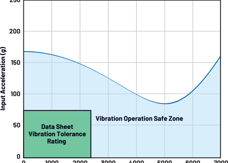
According to ADI, the sensor can withstand continuous random vibration with peak amplitudes up to 70 g over the 0 Hz to 2 kHz operating bandwidth. This specification reflects the sensor’s available mechanical headroom, illustrating that its usable operating margin depends not only on peak acceleration, but also on the frequency and spectral characteristics of the vibration.
This distinction also explains why shock ratings alone can be misleading. For example, the ADXL357B and ADXL380, despite their relatively low measurement ranges of ±40 g and ±16 g, share the same 10,000 g mechanical shock survivability rating as the high g ADXL373 (±400 g). However, identical shock survivability does not imply identical vibration tolerance. Because the ADXL373 has substantially greater mechanical headroom, it can accommodate much larger proof mass movement before approaching its mechanical limits, making it inherently more tolerant of sustained or high-energy vibration environments.
Newer sensors like the ADXL380 employ digital equalizer filters to extend their electrical bandwidth to 4 kHz. However, while digital filtering can improve what the sensor reports, it cannot change what the sensor experiences mechanically. A device can survive a high-g impact, report accurately across a wide bandwidth, and still face reliability risks if sustained vibration drives the proof mass toward its mechanical limits.
Conclusion
While not all MEMS applications require survivability beyond basic handling conditions, many high-reliability and high-dynamic systems do. In those environments, true survivability is not defined simply by whether a sensor remains physically intact after an event, but by whether it continues to meet its performance requirements once the event is over. ADI’s focus on vibration operating limits gives designers richer insight into how the sensor, package, and product architecture tolerate the actual mechanical environment over time.