
What Is TPS7A26?
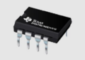
The TPS7A26 is a low-dropout (LDO) linear voltage regulator with a power-good (PG) output. It is designed to provide a stable, regulated output voltage for electronic circuits that require reliable power management. The device is available in fixed-output and adjustable-output versions, making it suitable for a wide range of applications.
The TPS7A26 features low quiescent current, which helps reduce power consumption and extend battery life in portable devices. Its adjustable version uses external feedback resistors to set the desired output voltage within the device’s specified operating range.

The power-good output indicates when the output voltage has reached the expected regulation level. This feature is useful in systems containing microcontrollers and other components that require a stable power supply before starting normal operation.
Block Diagram of TPS7A26
The internal block diagram illustrates the main functional sections of the regulator, including the voltage reference, error amplifier, pass element, current-limit circuit, thermal protection, undervoltage lockout, and power-good circuitry.
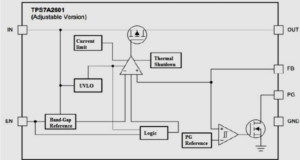
These functional blocks work together to maintain the regulated output voltage and protect the device under specified fault conditions.
Current Limit and Thermal Protection
The TPS7A26 includes an internal current-limit circuit that helps protect the regulator when the output current exceeds its specified limit. During current limiting, the device may no longer maintain the programmed output voltage. Excessive output current can increase power dissipation and cause the device temperature to rise. If the junction temperature reaches the thermal-shutdown threshold, the thermal protection circuit disables the regulator to help prevent damage.
The device can resume operation after its temperature falls below the specified recovery threshold, provided that the fault condition has been removed. The TPS7A26 also incorporates an undervoltage lockout (UVLO) circuit. This circuit monitors the input supply voltage and prevents normal operation when the input voltage is below the required threshold.
Functional Modes of TPS7A26
The operating behaviour of the TPS7A26 can be described using the following conditions:
1. Normal Operation
In normal operation, the input voltage is sufficient to maintain the programmed output voltage, and the output current remains within the device’s operating limits. The internal control circuitry regulates the output voltage to the required level.
2. Dropout Operation
Dropout occurs when the input voltage becomes too close to the required output voltage. In this condition, the regulator cannot maintain the programmed output voltage and the output begins to follow changes in the input voltage, subject to the device’s electrical characteristics.
3. Disabled Mode
When the regulator is disabled through its enable control, the output is switched off according to the device’s specified shutdown behaviour. This mode can help reduce power consumption when the regulated supply is not needed.
TPS7A26 Circuit Diagram
A typical TPS7A26 circuit includes an input supply, the regulator IC, input and output capacitors, and a load. In the adjustable-output version, an external resistor divider is also connected to the feedback terminal.
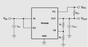
The input capacitor helps reduce input-supply disturbances, while the output capacitor supports stability and improves transient response. The power-good signal can be connected to a microcontroller or other monitoring circuit when required. For the correct connections and component values, follow the recommended application circuit in the manufacturer’s datasheet.
Adjustable Device Feedback Resistors
The adjustable-output version of the TPS7A26 uses two external feedback resistors, R1 and R2, to set the output voltage. The output voltage is calculated using the following equation:
VOUT = VFB × (1 + R1 / R2)
Where:
- VOUT: Desired output voltage.
- VFB: Feedback reference voltage specified in the datasheet.
- R1: Resistor connected between the output and feedback node.
- R2: Resistor connected between the feedback node and ground.
The resistor values must be selected according to the required output voltage and the regulator’s recommended feedback-resistor range. Use the feedback reference voltage specified for the exact TPS7A26 device version.
Recommended Capacitor Types
Suitable input and output capacitors are important for reliable operation of the TPS7A26. Capacitors with low equivalent series resistance (ESR) should be selected according to the manufacturer’s recommendations. Multilayer ceramic capacitors are commonly used in voltage-regulator circuits because of their compact size and low ESR. However, their effective capacitance can change with DC bias voltage, operating temperature, and capacitor type. Therefore, the capacitor’s nominal value alone may not represent its actual capacitance during operation. Select capacitors that meet the regulator’s stability requirements across the expected operating conditions.
Input and Output Capacitor Requirements
Input Capacitor
An input capacitor is recommended when the source impedance is greater than approximately 0.5 Ω, as stated in the applicable design guidance. It can help improve transient response, reduce input-voltage ripple, and support power-supply rejection performance. Place the input capacitor close to the regulator’s input and ground connections to minimize unwanted parasitic effects.
Output Capacitor
The output capacitor helps improve load-transient response and supports stable regulator operation. The recommended capacitance and ESR depend on the specific device requirements. A capacitance value below 50 µF may be suitable for particular configurations, but the final value should be selected from the manufacturer’s datasheet and application recommendations rather than treated as a universal limit.
Reverse Current Protection
The TPS7A26 does not provide dedicated reverse-current protection for every possible operating condition. If the output voltage can become higher than the input voltage, current may flow in an unintended direction and potentially damage the device. Applications that may experience reverse current should be evaluated carefully. Depending on the circuit, an external protection element or a suitable power-path arrangement may be required.
Features of TPS7A26
The important features of the TPS7A26 include:
- Low-dropout linear voltage regulation.
- Fixed-output and adjustable-output versions.
- Low quiescent current for power-conscious applications.
- Power-good output for monitoring the regulated supply.
- Internal current limiting.
- Thermal-shutdown protection.
- Undervoltage lockout.
- External feedback-resistor adjustment in the adjustable version.
- Support for compact power-supply designs.
Always refer to the official datasheet for the exact electrical limits, package details, and features available in the selected version.
Applications of TPS7A26
The TPS7A26 is suitable for electronic systems that require a regulated supply voltage and low power consumption. Typical application areas include:
- Home and building automation: Supplies regulated power to control circuits and electronic modules.
- Multicell power banks: Can be used in suitable auxiliary power-supply circuits.
- Smart grids and metering: Supports regulated power rails in compatible monitoring and measurement equipment.
- Portable power tools: Provides regulated power for suitable control electronics.
- Motor-drive systems: Powers control and interface circuits when its electrical ratings meet the design requirements.
- White goods: Can supply regulated power to compatible electronic control boards in household appliances.
- Portable appliances: Low quiescent current makes the device useful in battery-powered equipment.
- Microcontroller systems: Provides a regulated supply and a power-good indication for suitable digital circuits.
Advantages of TPS7A26
The TPS7A26 combines voltage regulation with power-good monitoring and integrated protection features. Its fixed and adjustable versions provide flexibility when designing power supplies for different circuits. Its low quiescent current can help reduce standby power consumption, while the current-limit, thermal-shutdown, and undervoltage-lockout circuits help protect the regulator during specified abnormal operating conditions.
Conclusion
The TPS7A26 is a low-dropout linear voltage regulator designed to provide a stable output supply for a variety of electronic applications. Its low quiescent current, power-good output, adjustable-output option, and integrated protection features make it useful in portable equipment, automation systems, metering devices, and microcontroller-based designs. For reliable performance, choose the appropriate device version, feedback resistors, and input/output capacitors according to the manufacturer’s datasheet. Correct component selection and circuit layout are essential for stable and safe operation.