Introduction
Arduino Redboard is a microcontroller board based on the ATmega328; it is an open-source microcontroller. It has different operating software Optiboot, as other Arduino board has bootloader operating software, but they have controlling system same as other Arduino boards. The Arduino Redboard is like a small portable computer. It is able of taking inputs and interpreting that information to control various outputs. The Arduino Redboard has 14 digital input and output pins out of these 14 pins, 6 are PWM (Pulse Width Modulation). It also has 6 analog input pins. It includes a power jack from where a supply is given to the board, it also has USB connection slot. And an RST button to rest the program of Arduino.
The RedBoard is an Arduino which is an able development platform that enables quick-and-easy project prototyping. It can interact with real-world sensors, control motors, display information, and perform near-instantaneous calculations. It also serves as an excellent physical computing learning platform. It is built to deal with both the programming and electronics world.
Technical specifications of RedBoard microcontroller
- Microcontroller: ATmega328 microcontroller with Optiboot (UNO) bootloader
- USB programming facilitated by the FTDI FT231X chip
- Input voltage: 7–15V
- Operating voltage: 0–5V outputs with 3.3V compatible inputs
- Digital Pins: 14 digital I/O pins (6 PWM outputs)
- Analog Pins: 6 analog inputs
- Header: 1 ISP header
- Memory: 32K flash memory
- Frequency: 16 MHz
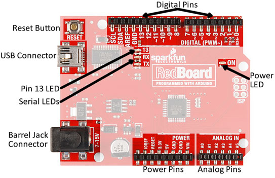
Arduino redboard pin configuration
Digital pins: The digital pins of the board are the digital inputs and outputs pins. These are the pins that connect to buttons, LEDs, sensors, etc. to interface the Arduino with other pieces of the hardware system. There are a total of 14 digital pins on the board. Out of these all 14 pins, 6 are PWM (Pulse Width Modulation). Pins marked with a tilde (~) can also serve as analog outputs, which you can use to dim LEDs or run servo motors.
Analog Pins: The board has a total of six analog input pins. These all pins have analog-to-digital converters which can be used to read in an analog voltage between 0 to 5V. These are useful if you need to read the output of a potentiometer or other analog sensors. All six analog pins can also serve as digital inputs and output pins.
Power Pins
These pins are traditionally used as power sources.
- VIN: VIN pin is the input voltage pin of the board; it has a range of 7volts to 15 volts. The voltage provided using the power jack can be accessed by this VIN pin. However, the output voltage through this pin to the board will be automatically set up to 5V.
- PIN 3.3V & 5V: These are the pins that are used to provide an output regulated voltage of approximately 5V. This regulated power supply gives power to the microcontroller as well as to all the other components used over the Arduino Mega board. The maximum power that can be drawn from this board is 50Ma.
- GND Pin: The Arduino Mega 2560 board has 5 ground pins from where we can use any pin as required in projects.
- RST Pin: The REST pin of this Mega board is used to rearrange the board.
LED
- The Arduino Mega board has a LED that is connected to pin-13 which is named digital pin 13. This LED can be operated based on the high value and low value of the pin.
AREF
- The AREF (Analog Reference Voltage) pin works for reference voltage for analog inputs.
- Serial Communication: TXD and RXD are the serial pins of the board, they are used to transmit & receive the serial data. Where Tx indicates the transfer of data whereas the Rx indicates receiving of data.
ADVANTAGES OF ARDUINO REDBOARD
- It has a USB connection slot.
- It has less pins, hence it is less complex.