- Asynchronous counters are those that do not use simultaneous clocking. Only the first flip-flop in an asynchronous counter is externally clocked with a clock pulse, while the clock input for subsequent flip-flops is the output of a previous flip-flop.
- This means that a single clock pulse is not driving all of the flip-flops in the counter’s configuration.
- Asynchronous counters, also known as ripple counters, are made up of a series of trailing edge-triggered flip-flops. It is so named because data ripples from one flip-output flop to the next’s input.
- T flip-flops are used in the design of the asynchronous counter. Because the output of the T flip-flop toggles. In other words, the output of this flip-flop is complimentary. In other words, if 0 is given as input, 1 is produced as output, and vice versa.
- Negative edge-triggered flip-flops are used in the asynchronous counter. This means that the flip-flop will change its state on the clock pulse’s falling edge.
Different Types of Asynchronous Counters
1. 2-bit Asynchronous Up Counter
- Two flip-flops are used to create a 2-bit asynchronous counter, as shown in the figure below. It is an up counter, with the count increasing with each clock pulse. A two-bit counter has 22 = 4 distinct states (00, 01, 10, 11).
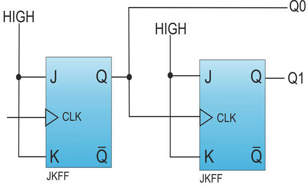
- Only the first flip-flop receives the clock pulse input. The first flip-output flop (QA) is used as the clock input for the second flip-flop. At the T-input of both flip-flops, the HIGH or logic 1 is maintained.
- The clock pulse is counted digitally at the outputs QA and QB, where QA is the least significant bit (LSB) and QB is the most significant bit (QB) (MSB).
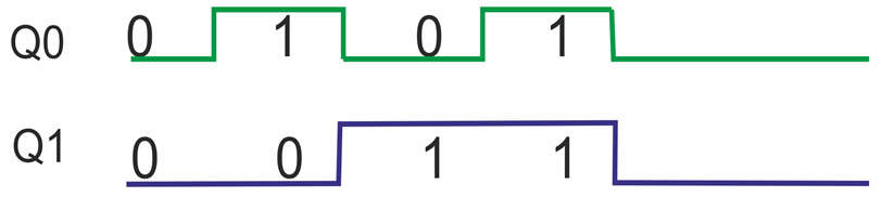
- Assume the flip-initial flop’s state is QBQA = 00. JK FF1 will toggle its output state to logic 1 during the first clock pulse, that is, at the falling edge of the clock pulse. JK FF1 will again toggle its output to logic 0 for the next clock pulse. JK FF1 continues to be toggled for each clock pulse.
- The first flip-output flop (JK FF1) is used as a clock pulse input for the second flip-flop (JK FF2). When the QA output goes high, the JK FF2 is triggered at the falling edge of its output. When the JK FF2 is activated, it generates a toggled output.
- Because we assumed that JK FF2’s initial state was QB = 0, the output will be toggled to QB = 1. When the output of JK FF1 goes HIGH, this output toggles once more.
- The timing diagram below depicts the change in the state of flip-flops for each occurrence of the clock pulse. The counter counts from o0 to 11, as shown in the timing diagram. When the counter reaches 11, it resets to 00 and begins counting again from 00.

ADVERTISEMENT
2. Four-bit “Up” Counter
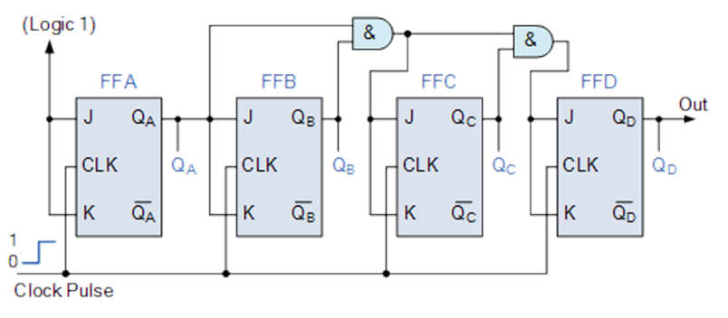
- When “clocked” by a repetitive source of pulses from an oscillator, this circuit would produce the following output waveforms:
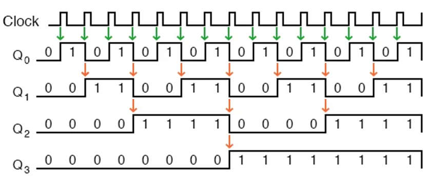
- The first flip-flop (the one with the Q0 output) has a clock input that is positive-edge triggered, so it toggles with each rising edge of the clock signal.
- Take note of how the duty cycle of the clock signal in this example is less than 50%.
- I’ve shown the signal in this manner to demonstrate how the clock signal does not have to be symmetrical to produce reliable, “clean” output bits in our four-bit binary sequence.
- I used the clock signal as one of the output bits in the very first flip-flop circuit shown in this chapter.
- However, this is a bad practice in counter design because it requires the use of a square wave signal with a 50% duty cycle (“high” time = “low” time) to obtain a count sequence in which each step pauses for the same amount of time.
- Using one J-K flip-flop for each output bit, on the other hand, eliminates the need for a symmetrical clock signal, allowing us to use virtually any high/low waveform to increment the count sequence.
- Each succeeding output bit is toggled by the action of the preceding bit transitioning from “high” (1) to “low,” as indicated by all of the other arrows in the pulse diagram (0).
- This is the pattern required to produce an “up” count sequence.
- To generate an “up” sequence using positive-edge triggered flip-flops, a less obvious solution is to “clock” each flip-flop using the Q output of the preceding flip-flop rather than the Q output.
- Because the Q’ output on a J-K flip-flop is always the exact opposite state of the Q output (there are no invalid states with this type of flip-flop), a high-to-low transition on the Q output is accompanied by a low-to-high transition on the Q’ output.
- In other words, whenever the Q output of a flip-flop changes from 1 to 0, the Q’ output of the same flip-flop changes from 0 to 1, supplying the positive-going clock pulse required to toggle a positive-edge triggered flip-flop at the appropriate time.
3. Asynchronous 3-bit Up/Down Counters
- We can create an asynchronous up/down counter by combining the concepts of a UP counter and a DOWN counter. The three-bit asynchronous up/down counter is depicted below.
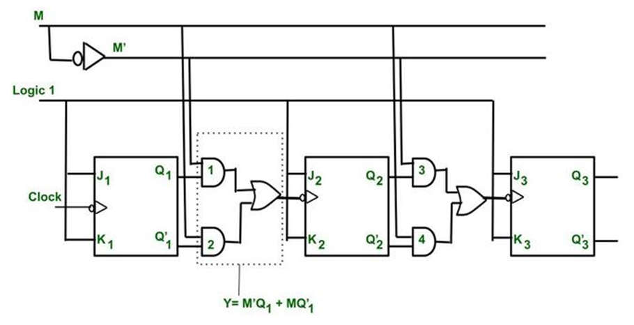
- Based on the clock signal input, it can count in either direction, up to down or down to up.
UP Counting
- If the UP and DOWN inputs are both 1, then the NAND gates between the first and third flip flops will pass the non-inverted output of FF 0 to the clock input of FF 1. Similarly, FF 1’s Q output will be routed to FF 2’s clock input. As a result, the UP/down counter performs up counting.
DOWN Counting
- If the DOWN and UP inputs are both 1, then the NAND gates between the first and third flip flops will pass the inverted output of FF 0 to the clock input of FF 1. Similarly, FF 1’s Q output will be routed to FF 2’s clock input. As a result, the UP/down counter performs down counting.
- Because the additional propagation delay is added to the NAND gate network, the up/down counter is slower than an up counter or a down counter.
Case 1: If M = 0, then M’ = 1.
- Fill in the blanks: Y= M’Q + MQ’= Q As a result, Q serves as a timer for the next FFS.
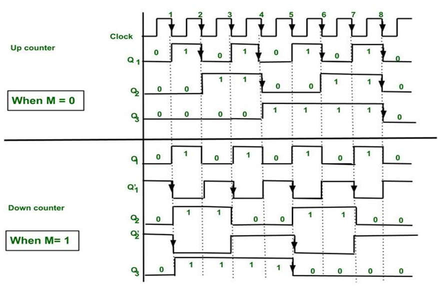
- As a result, the counter will function as an Up counter.
Up Counter Explanation
- The first FF is linked to logic 1. As a result, it will toggle for each falling edge.
- Q1 is connected to the second FF input.
- As a result, it changes its state when Q1 = 1 and the clock is falling.
- Similarly, the third FF is linked to Q2. As a result, it changes its state when Q2 = 1 and the clock is falling.
- This allows us to generate counting states for the Up counter.
- After every eighth falling edge, the counter returns to 0 0 0. As a result, it is also known as the divide by 8 circuits or the mod 8 counter.
Case 2: If M = 1, then M’ = 0.
- Fill in the blanks with Y= M’Q + MQ’= Q’. As a result, Q’ serves as a timer for the next FFS. As a result, the counter will function as a Down counter.
Down Counter Explanation
- The first FF is linked to logic 1. As a result, it will toggle for each falling edge.
- Q’1 is connected to the second FF input.
- As a result, it changes its state when Q’1 = 1 and the clock is falling.
- Similarly, the third FF is linked to Q’2. As a result, it changes state when Q’2 = 1 and the clock’s falling edge is present.
- This allows us to generate down counter counting states.
- After every eighth falling edge, the counter returns to 0 0 0.
- As a result, it is also known as the divide by 8 circuits or the mod 8 counter.
Advantages of Asynchronous Counter
- It is simple to design using a D-flip flop or a T-flip flop.
- It is suitable for use in low-speed circuits.
- It is employed as a Divide by-n counter.
- They can also function as Truncated counters. (to create any mod number counters, such as Mod 4, and Mod 3).
Disadvantages of Asynchronous Counter
- Extra flip-flops are required for re-synchronization.
- To count the sequence of truncated counters, additional feedback logic is required (keep in mind that mod is not equal to 2n).
- While counting a large number of bits, asynchronous counters have a very long propagation delay.
- Counting errors may occur at high clock frequencies due to propagation delay.
- They are slower than synchronous counters.
Applications of Asynchronous Counter
- They serve as frequency dividers as well as divide by “N” counters.
- They are used in low-noise, low-power applications.
- They are used in the creation of an asynchronous decade counter.
- It is also employed in the Ring counter and the Johnson counter.
- Mod N ripple counters employ asynchronous counters. Mod 3, Mod 4, Mod 8, Mod 14, Mod 10, and so on.