- There are several methods for displaying the audio level of a signal, one of which is to use sound pressure level meters, which simply calculate the change in pressure of the sound signal. They are based on the fact that different frequencies of sound have different pressure levels.
- Another method is to have a visual representation of the loudness of the audio signal. Normally, the display takes the form of a series of LEDs that light up sequentially to indicate the level of the audio signal.
- The magnitude of the sound signal perceived by each individual such that the person can bear the sound pressure is referred to as loudness. The loudness of the sound varies with frequency for the same pressure.
- The two methods described above use decibels to measure the loudness or volume of a sound. One decibel is equal to ten times the logarithm of the sound signal’s power. Because a large scale for direct measurement is usually impractical, the scale is usually displayed in decibels or dB.
- Before we get into the specifics of the visualized audio level meter, let us first review the LM3915.
LM3915
- The LM3915 is a dot/bar display driver that uses an analog input to drive a series of LEDs. It essentially drives each adjacent LED in 3DB steps or a logarithmic manner. It is powered by a 3 V to 25 V supply voltage.
LM3915 Pin Description
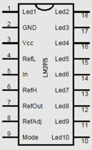
- Pins 1, 10 to 18: Each of these pins is connected to the cathode of the output LED. The anode of the output LEDs is connected to the 3V to 20V supply.
- Pin 2 is the negative analog voltage supply and is typically connected to the ground.
- Pin 3: This is the positive voltage supply pin, and the supply voltage is typically between 3 and 20 volts.
- Pin 4: Normally, this pin is grounded.
- Pin 5: This is the signal input pin, and it receives audio signal input.
- Pins 6 and 7 are both shorted together. The current drawn by each LED is determined by the current drawn through pin 7.
- Pin 8: This is the reference voltage adjustment pin. A resistance of 1.2kohms exists between pins 7 and 8, resulting in a voltage of 1.25V between the pins. A resistor is connected to a potential divider, which is used to adjust the reference voltage.
- Pin 9 is the mode select pin, and it is used to choose between the dot and bar modes. The pin is connected directly to pin 3 for the bar mode, i.e. to the positive voltage supply. The pin is left open in dot mode, with no connection.
LM3915 as an Audio Level Meter
- This circuit makes use of only one integrated circuit and a few external components. It displays the sound/audio level using up to ten LEDs. The input voltage can range from 12V to 20V, but we are only using 12V. The chip contains a flexible voltage reference as well as a precise ten-stage voltage divider. The high-impedance input buffer accepts signals as low as ground and as high as 1.5v from the positive power supply. Furthermore, it does not require protection against 35V inputs. The input buffer powers ten distinct comparators that are linked to the accuracy divider. Normally, accuracy exceeds 1dB.
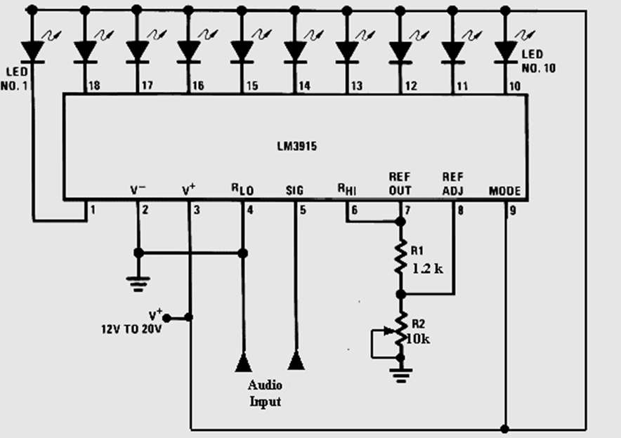
- When using the dot mode, the LED that is illuminated represents the audio waveform’s instantaneous value. Peak and average levels are easily visible. Because the dot will be moving constantly, the LEDs are set to 30mA to provide enough power. The full-scale reading is 10 volts, which can be easily adjusted by adjusting resistor R2. The signal input of the LM3915 can withstand signals of up to 35 volts. If the audio input has a chance of exceeding this range, attenuate it or include enough series resistance to limit the current to 5mA.
Applications
- Audio Visualization Circuit.
- Crude battery indicator.
- Low-cost monitoring equipment.
- Digital meter.
- Electronic display.
- Fade in and fade out bar.