- TLE4275-Q1 is a voltage regulator with a low dropout. It is a monolithic integrated circuit. This device can convert voltages as high as 45V to a 5V output voltage. TLE4275-Q1 has a maximum load current of 450mA. When overheating is detected, the temperature protection circuit in the device shuts it down to protect it from damage caused by high temperatures.
- External capacitors are used in conjunction with the IC for stability and high transient responses. The operating junction temperature ranges from -400°C to 1500°C. TLE4275-Q1 has a 5mA output current. The minimum input voltage under recommended operating conditions is 5.5V.
Block Diagram
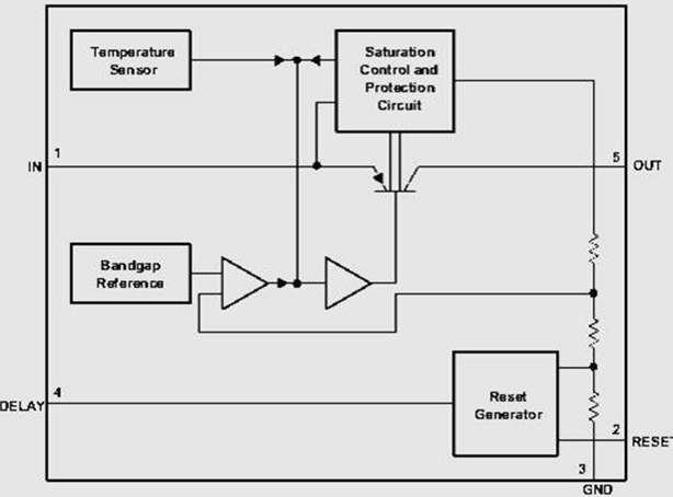
- Over temperature protection circuit and overload protection circuit are included in the TLE4275-Q1 block diagram.

Regulated Output:
- The device provides a regulated 5V output that can be drawn using the OUT pin. The output is subject to a current limitation. This regulator has a soft start built in to control the initial current through the pass element during power up.
Power on Reset (RESET):
- RESET is connected to the regulated supply via an external pull-up resistor. The reset output remains low until the regulator load voltage exceeds approximately 4.65V and the power on the Reset delay has expired.
Reset Delay Timer (DELAY):
- An external capacitor on this DELAY terminal sets the timer delay before the reset terminal is asserted high. To trip an internal comparator, charge the external capacitor until the voltage exceeds the threshold value. A constant output current is used to charge the external capacitor.
Low voltage Tracking Mode:
- When the input voltage is low, the regulator loses control. At this point, the output voltage follows the input voltage minus a voltage determined by the load current and switch resistance. This eliminates the need for a boost converter when starting the engine cold.
Circuit Diagram of TLE4275
- Various external component values are used in conjunction with the TLE4275-Q1 voltage regulator IC, depending on the application. Large output capacitors are used to prevent the reset during fast load steps.
![]()
- A low-ESR ceramic capacitor with a dielectric of type X5R or X7R is recommended for improved load transients. Some parameters should be determined before beginning the design process.
- Input voltage range, output voltage range, output current rating, output capacitor, and power-up reset delay time are some examples. An input voltage range of 4 to 40V is used for the circuit above. The output voltage in this case is 5V.
- The output current is rated at 400mA, and the output capacitor range is 10 to 500F. The ESR range for the output capacitors used in the circuit is 1m to 20 and the DELAY range is 100pF to 500nF. When the device becomes too hot, the temperature protection circuit shuts it down.
- The device’s input supply should be well regulated. If the input supply is more than a few inches away from the IC, it is recommended that an electrolytic capacitor of 47F and a ceramic by-pass capacitor be added at the input.
Pin Configuration of TLE4275
- The TLE4275-Q1 voltage regulator is available in five-pin TO-263-KTT, five-pin TO-252-KVU, and twenty-pin HTSSOP-PWP packages. The pin configuration of the KTT and KVU packages is similar.
![]()
The pinout for the KTT and KVU packages is as follows
- Pin-1 is the IN (input) pin. It is grounded through the use of a ceramic capacitor.
- RESET is the Reset output pin on Pin-2. This is also referred to as Open-collector Output.
- GND is the ground pin on pin-3. This pin is connected to the heat sink internally.
- DELAY is the delay rest pin on pin-4. This pin is connected to the ground via a capacitor to set the delay time.
- Pin-5 is the OUT (output) pin. A capacitor larger than 22F is used to connect this pin to the ground.
The 20-Pin PWP package’s pin configuration is as follows.
- RESET is the reset output pin on Pin-1.
- Pin-3 is the DELAY reset delay pin.
- Pin-4 is the OUT (output) pin.
- GND is the ground pin on pin-8.
- Input pin IN is pin 19.
- Pins 2, 5, 6, 7, 9, 10, 11, 12, 13, 14, 15, 16, 17, 18, and 20 are all NC pins with no connections.
Specifications of TLE4275-Q1
- TLE4275-Q1 is a monolithic integrated circuit.
- It has an extremely low dropout voltage.
- It consumes very little power.
- This device can be used in automotive applications.
- TLE4275-Q1 has a 5V output voltage.
- It includes a short-circuit protection circuit.
- There is a power-on and an Under voltage reset button.
- The low-level output voltage of the reset is less than 1V.
- TLE4275-Q1 is reverse polarity resistant.
- Over-temperature and overload protection circuits are also included in the TLE4275-Q1.
- It has an external delay capacitor that is used to program the rest delay.
- TLE4275-Q1 comes in a 5-pin TO package.
- TLE4275-Q1 can regulate 45V input voltage.
Applications of TLE4275-Q1
- The TLE4275-Q1 voltage regulator is approved for use in automotive applications.
- This device can also be used as a Cluster.
- TLE4275-Q1 low dropout voltage regulator is used in body control modules.
- A TLE4275-Q1 voltage regulator is used in heating, ventilation, and air conditioning (HVAC).
