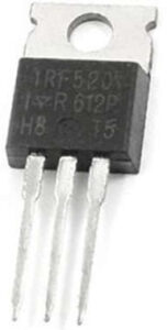
- The IRF520 MOSFET is a third-generation power MOSFET that offers fast switching, low resistance, and low cost. TO-220AB, the universally preferred package, is used in all industrial and commercial applications with power dissipation levels of up to 50 W.
- A power MOSFET with a collector current of 9.2A and a breakdown voltage of -100V is available, such as the IRF520. This MOSFET has a lower gate threshold voltage of 4V and is thus normally used by different microcontrollers to activate high current loads.
- This transistor can switch various loads while consuming 9.2A of continuous current and operating at 100V. It also has 0.27 Ohms of on-state resistance, which improves MOSFET efficiency by dissolving low heat-like loss. Because this MOSFET has a low gate threshold voltage of only 4V, it can be switched ON even with 5V from the microcontroller’s GPIO pin.
- However, this does not imply that the transistor will be fully activated with just 5V; it requires approximately 10V supplied to the gate pin to fully activate and supply 9.2A of collector current. As a result, if you are looking for a MOSFET to use with a microcontroller, the 2N7002 MOSFET should be considered.
- You can also use a driver circuit to provide 10V to the gate pin of this Mosfet via a transistor. Furthermore, the MOSFET has fast switching speeds and can thus be used in DC-DC converter circuits.
Pin Configuration
- The pinout of the IRF520 MOSFET is shown below. This transistor has three terminals, and each terminal’s functionality is discussed below.
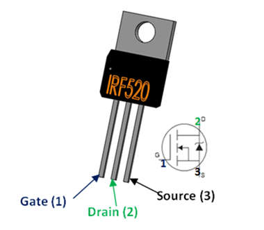
- Pin1 (Source): Current supplies out throughout the source terminal.
- Pin2 (Gate): This terminal controls the MOSFET biasing.
- Pin3(Drain): Current supplies throughout this drain terminal.
How to use IRF520 MOSFET?
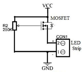
- An LED strip dimmer circuit is built using an IRF520 MOSFET. IRF520 MOSFET-1, LED strip-1, Potentiometer-1, 9V battery-1, Resistance-1, fabrication machines, hand tools, soldering iron, and nose pliers are required to build this circuit.
The Procedure for Connecting the Circuit
- A 250k potentiometer is used in the first step to change the voltage of a DC dimmer Board.
- Step 2: Fix the potentiometer in place and solder the three terminals to the LED Dimmer.
- In step 3, an IRF520 is used to provide the highest o/p of a simple LED dimmer circuit. This circuit can also be used with other N-channel MOSFETs.
- Connect the potentiometer to the MOSFET in step 4. The gate pin of this transistor is connected to the potentiometer’s middle pin, and the drain pin is connected to the potentiometer’s corner pin.
- In step 5, primarily use a 12V single color LED strip for a PWM LED strip dimmer.
- In step 6, the +ve wire of the LED strip is connected to the MOSFET’s source pin, and the -Ve wire is connected to the potentiometer’s first pin.
- Finally, a 12V SMPS is used to supply 12v power to the strip dimmer circuit.
- This LED dimmer circuit has only two components: a potentiometer and an IRF520 MOSFET. This MOSFET is an Enhancement type that provides maximum o/p and can also be used in conjunction with another N-Channel MOSFET.
- The potentiometer is connected to the gate terminal of the MOSFET in this simple led dimmer circuit. The gate voltage can be adjusted here by rotating the potentiometer.
- The voltage from the Drain to the Source must change for the voltage at the Gate terminal to change. As a result, the voltage will change constantly as the potentiometer is rotated. As a result, the above led dimmer circuit will function with the assistance of a potentiometer.
- This LED strip dimmer circuit can be found in a variety of applications. Using this board, we can build a 100W LED dimmer circuit as well as a motor speed controller. The components used in this circuit are inexpensive and widely available in most markets. A similar type of security protection is frequently implemented using various Microcontrollers such as the Raspberry Pi, Arduino, PIC, and many other controllers. They are, however, not cheap.
Applications of IRF520 MOSFET
- IRF520 MOSFETs are used in a wide variety of circuits such as current UPS, motor controller circuits, and low power supplies, and can also be used to drive high-power components such as transistors, relays, and so on.
- Because it has fewer gate power supplies, it is only used to drive high current loads at the o/p of raspberry pi, Arduino, and other ICs.
- It is used in audio amplifier circuits.
- Motor Driver Circuits.
- DC-DC converters.
- Telecommunication & Computer Applications.
- Fast Switching Applications.
- Applications of Solar.
- UPS or Uninterruptible power supplies.
- Management Systems of Battery.
- Chargers of Battery.
Advantages
The advantages of IRF520 MOSFET include the following.

ADVERTISEMENT
- High current capacity.
- Gate charge is less.
- 100% tested with an avalanche.
- The operating temperature is 175oC.
- The technology used is avalanche rugged.