Introduction
The most effective way to analyze the behavior of components in an AC circuit is by using phasors, especially when all circuit elements operate at the same frequency. Phasors help represent sinusoidal quantities and simplify the analysis of voltage and current relationships.
When two phasors are added together, their resultant value depends on their relative phase positions, whether they are in-phase or out-of-phase. This difference in angular position between two sinusoidal waveforms is known as the phase difference or phase shift.
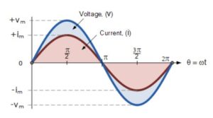
Sinusoidal waveforms are graphical representations of alternating quantities plotted against time. A sinusoidal waveform reaches its maximum positive value at π/2 radians, its maximum negative value at 3π/2 radians, and crosses the zero axis at 0, π, and 2π radians.
What is Phase Difference?
Phase difference refers to the angular displacement between two sinusoidal waveforms having the same frequency. It indicates how much one waveform leads or lags another waveform. If two waveforms reach their maximum, minimum, and zero values simultaneously, they are said to be in phase. If they reach these values at different times, they are considered out of phase.
Phase Difference Equation
The general equation of a sinusoidal waveform is:
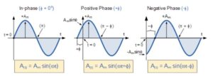
A(t) = Amax × sin(ωt ± φ)
Where:
- Amax = Amplitude of the waveform
- ωt = Angular frequency of the waveform in radians per second
- φ (phi) = Phase angle in degrees or radians by which the waveform shifts left or right from the reference waveform
What is Phase Shift?
Phase shift is the amount by which a waveform is displaced from a reference waveform along the horizontal time axis. The phase shift may be:
- Positive (+φ): The waveform leads the reference waveform.
- Negative (-φ): The waveform lags behind the reference waveform.
Phase shift is generally measured in degrees (°) or radians.
Phase Relationship of a Sinusoidal Waveform
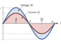
For sinusoidal waveforms operating at the same frequency, the angular rotation during each cycle remains constant. Therefore, the phase difference between two quantities also remains constant. Consider two alternating quantities: voltage (V) and current (I).
If both waveforms reach their positive peak, negative peak, and zero-crossing points simultaneously, then:
φ = 0°
In this case, the voltage and current are said to be in phase.
Two Sinusoidal Waveforms in Phase
When two sinusoidal waveforms have zero phase difference, they are called in-phase waveforms.
They possess:
- The same frequency
- The same period
- Simultaneous positive peaks
- Simultaneous negative peaks
- Simultaneous zero crossings
Examples of in-phase waveforms are commonly found in purely resistive AC circuits.
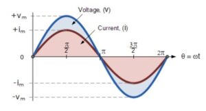
Two Sinusoidal Waveforms Out of Phase
Suppose the voltage and current waveforms have a phase difference of 30°:
φ = 30° = π/6 radians
Since both waveforms have the same frequency, the phase difference remains constant throughout the cycle. One waveform will either lead or lag the other by 30°.
- If the current reaches its peak before the voltage, the current leads the voltage.
- If the voltage reaches its peak before the current, the current lags the voltage.
Leading and Lagging Phase Difference
Leading Phase Angle
A waveform is said to be leading when it reaches a particular point in the cycle before the reference waveform. Example: In a capacitive circuit, current leads voltage.
Lagging Phase Angle
A waveform is said to be lagging when it reaches a particular point in the cycle after the reference waveform. Example: In an inductive circuit, current lags voltage.
Phase Difference in AC Circuits
The phase relationship between voltage and current depends upon the type of circuit component:
| Circuit Element | Phase Relationship |
|---|---|
| Resistor (R) | Voltage and Current are in phase (0°) |
| Inductor (L) | Current lags Voltage by 90° |
| Capacitor (C) | Current leads Voltage by 90° |
Advantages of Phase Difference Analysis
- Simplifies AC circuit analysis.
- Helps determine power factor.
- Allows calculation of impedance.
- Assists in analyzing circuit behavior using phasors.
- Improves understanding of voltage-current relationships.
Applications of Phase Difference and Phase Shift
- AC circuit analysis.
- Power factor correction systems.
- Electrical power transmission.
- Oscillators and signal generators.
- Communication systems.
- Phase-sensitive detectors.
- Motor control circuits.
- Radar and navigation systems.
- Digital signal processing.
- Instrumentation and measurement systems.
Conclusion
Phase difference and phase shift are fundamental concepts in alternating current systems. They describe the angular relationship between two sinusoidal waveforms operating at the same frequency. Understanding phase relationships is essential for analyzing AC circuits, calculating power factors, designing communication systems, and controlling electrical machines efficiently.