

Introduction
Resistors are passive electrical components that dissipate electrical energy, primarily in the form of heat. They do not generate electrical energy. In DC circuits, the resistance of a resistor is defined by the linear relationship between its voltage and current. In AC circuits, the relationship between voltage and current is also important because the voltage and current can have a phase difference. However, for an ideal resistor, the voltage and current remain in phase, and the resistance does not depend on the AC supply frequency.
Resistance and Impedance in AC Circuits
For an ideal resistor, the impedance is purely resistive. Therefore:

Z = R
Where:
- Z = Impedance in ohms (Ω)
- R = Resistance in ohms (Ω)

Unlike capacitors and inductors, an ideal resistor has the same resistance regardless of the supply frequency, from DC through high-frequency operation. In practical circuits, however, real resistors can exhibit small parasitic inductive and capacitive effects at very high frequencies.
V-I Phase Relationship in a Resistor
The direction of current through a resistor in an AC circuit does not change the fundamental behaviour of an ideal resistor. The current changes in response to changes in voltage.
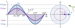 For a purely resistive AC circuit, the voltage and current reach their maximum and minimum values at the same instant and cross zero at the same instant. Therefore, the voltage and current are said to be in phase.
V-I Phase Relationship and Vector Diagram
Because the voltage and current reach their maximum values at the same time, the phase angle between them is:
φ = 0°
Therefore, the instantaneous voltage and current are in phase at every point of the AC cycle. Ohm’s Law can be used to determine the resistance from the voltage and current values.
AC Circuit with a Resistor
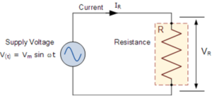
Consider an AC circuit consisting of a resistor connected to an AC voltage source. The instantaneous voltage across the resistor, VR, is equal to the applied supply voltage and can be expressed as:
VR = Vmax sin(ωt)
According to Ohm’s Law, the instantaneous current flowing through the resistor is:
I = VR/R
Therefore:
I = Imax sin(ωt)
Since the voltage across a resistor is given by:
VR = I R
the instantaneous voltage can also be written as:
VR = Imax R sin(ωt)
Resistors in AC Series Circuits
In a purely resistive series AC circuit, the voltage across each resistor is in phase with the current. Therefore, the individual voltage drops can be added together to determine the total circuit voltage. For resistors connected in series:
RT = R1 + R2 + R3 + …
The total voltage is related to the total resistance and current by Ohm’s Law:
VT = I RT
Resistors in AC Parallel Circuits
In a purely resistive parallel AC circuit, the currents in the individual branches are all in phase with their corresponding branch voltages. Therefore, the branch currents can be added together to determine the total circuit current:
IT = I1 + I2 + I3 + …
Power Factor of a Resistive AC Circuit
For a purely resistive circuit, the phase angle between voltage and current is zero:
φ = 0°
Therefore, the power factor is:
cos(φ) = cos(0°) = 1
This means that a purely resistive AC circuit has a power factor of 1.0.
Power in a Resistive AC Circuit
The instantaneous power in an AC circuit is obtained by multiplying the instantaneous voltage and current:
p(t) = v(t)i(t)
For an AC circuit, the average real power is:
P = Vrms Irms cos(φ)
For a purely resistive circuit, cos(φ) = 1. Therefore:
P = Vrms Irms
Using Ohm’s Law, the power can also be expressed as:
P = Irms2R
or:
P = Vrms2/R
Power Waveform in a Pure Resistance
The instantaneous power waveform of a purely resistive AC circuit consists of positive pulses. This occurs because voltage and current are in phase.
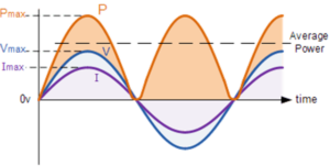
During the positive half-cycle, both voltage and current are positive, so their product is positive. During the negative half-cycle, both voltage and current are negative, and the product is again positive. Therefore, the resistor continuously absorbs power from the AC source and converts the electrical energy primarily into heat.
AC Power and RMS Values
The power dissipated by a purely resistive load connected to an AC RMS supply is given by:
P = Vrms Irms
It can also be calculated using:
P = Irms2R
or:
P = Vrms2/R
Where:
- P = Average power in watts (W)
- Vrms = RMS supply voltage in volts (V)
- Irms = RMS supply current in amperes (A)
- R = Resistance in ohms (Ω)
Importance of RMS Values
An AC current with a maximum value of Imax does not produce the same heating effect as a DC current having the same numerical value.

Therefore, RMS values are used when comparing the heating effect of an AC current with an equivalent DC current.
Applications of Resistors in AC Circuits
Resistors are widely used in AC circuits where electrical energy needs to be converted into heat or where current and voltage need to be controlled. Common examples of resistive AC loads include:
- Electric heaters
- Water heaters
- Electric irons
- Toasters
- Electric fires
- Heating elements
- Electric kettles
Conclusion
In a purely resistive AC circuit, the voltage and current are in phase, resulting in a phase angle of 0° and a power factor of 1. The impedance of an ideal resistor is equal to its resistance, so Z = R. The average power consumed by a resistor in an AC circuit can be calculated using RMS voltage and current. Because a resistor dissipates electrical energy as heat, resistive AC circuits are widely used in heating applications such as heaters, irons, kettles, toasters, and water heaters.