

Introduction
High-Frequency (HF) radio communication systems rely on effective signal transmission between the radio transceiver and the antenna. However, physical antennas rarely present a perfect electrical match across every frequency band. To overcome this impedance mismatch and prevent lost transmitter power, radio operators utilize an Antenna Tuner—also known as an Antenna Tuning Unit (ATU) or Transmatch.
What is an Antenna Tuner?
An antenna tuner is an impedance-matching network connected between a radio transmitter (or receiver) and its antenna system. Its primary function is to adjust the complex electrical impedance seen by the transmitter so that it matches the radio’s required output impedance (typically 50 ohms).

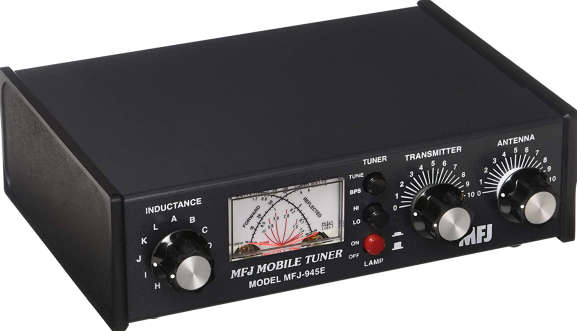
Antenna tuning units are critical components across various radio communication setups, including amateur (ham) radio stations, commercial broadcast facilities, maritime vessels, and military HF communications networks.
Alternative Names for Antenna Tuners
Depending on the industry, region, or specific application, an antenna tuner is referred to by several names:
- ATU: Antenna Tuning Unit / Antenna Unit
- Transmatch: A term commonly used in ham radio for transmitter-matching networks
- Matchbox: Informal term for standalone manual antenna matching units
- Antenna Coupler / Feed Line Coupler: Often used when the matching unit is mounted outdoors at the antenna base
- Impedance Matching Unit: Technical description emphasizing its electrical function
Why is Antenna Tuning Necessary?
For a transmitter to deliver maximum power to an antenna, the output impedance of the transmitter must equal the input impedance of the feedline and antenna system (governed by the Maximum Power Transfer Theorem). Most modern HF transceivers are designed for a fixed load of 50 ohms resistive. However, an antenna’s real-world impedance fluctuates significantly based on several factors:
- Operating frequency changes
- Physical height above ground
- Proximity to nearby metal structures or trees
- Antenna length relative to wavelength
When an impedance mismatch occurs, a portion of the transmitted power is reflected backward toward the radio as a standing wave. This causes a high SWR (Standing Wave Ratio). High SWR reduces radiated signal strength and can generate excess heat, potentially damaging the transmitter’s final amplifier transistors.
How Does an Antenna Tuner Work?
An antenna tuner does not physically change the length or resonance of the wire antenna outside. Instead, it acts as an adjustable electrical transformer or conjugate matcher. An ATU contains adjustable reactive components—specifically variable capacitors and variable inductors (coils) arranged in specific circuit topologies (such as L-networks, Pi-networks, or T-networks):
- Inductive Reactance ($X_L$): Used to cancel out capacitive reactance in the antenna system.
- Capacitive Reactance ($X_C$): Used to cancel out inductive reactance in the antenna system.
By adjusting these internal capacitors and inductors, the tuner creates an equal and opposite electrical reactance. This cancels out the mismatch, transforming the complex antenna load into a clean 50-ohm load at the transmitter terminals.
Manual vs. Automatic Antenna Tuners
1. Manual Antenna Tuners
Manual tuners feature physical knobs connected to variable capacitors and rotary inductors. The operator transmits a low-power tone while manually adjusting the controls until an onboard SWR meter indicates a $1:1$ match.
2. Automatic Antenna Tuners (Auto-Tuners)
Automatic tuners use built-in microcontrollers, directional couplers, and high-speed relay banks to switch fixed capacitors and inductors in milliseconds. When the radio keys up, the microprocessor senses the SWR, calculates the required matching combination, and engages the appropriate relays automatically.
Where is the ATU Located?
An antenna tuner can be placed in two primary locations within a station setup:
- At the Transmitter (Shack-Mounted): Located inside or right next to the radio. This protects the transmitter and allows full power output, though power loss may still occur along a long coaxial feedline.
- At the Antenna Feed Point (Remote Mount): Mounted directly at the base of the antenna or wire junction. This is the most efficient configuration because it matches impedance before the feedline, eliminating standing waves and minimizing coaxial line losses.
Key Benefits of Using an Antenna Tuner
- Transmitter Protection: Prevents high SWR fold-back circuits from throttling power output or damaging final RF amplifiers.
- Multi-Band Capability: Allows a single physical antenna (like a dipole or end-fed wire) to operate across multiple HF frequency bands.
- Improved Reception: Helps filter out out-of-band signals and noise before reaching the receiver front-end.
- Operational Flexibility: Enables reliable communications under field or emergency conditions where ideal antenna installations are not possible.