- Thermocouples are temperature sensors that are extensively used for the measurement of temperature variations. They sense the temperature and the temperature is further measured by other instruments after sensing it.
- As they convert a non-electrical quantity (temperature) into voltage (electrical quantity) so they are transducers also. Since they do not require any external power source to operate, so they are active transducers.
Working Principle of Thermocouple
- The thermocouple working principle is based on the Seeback Effect. This effect states that when a closed circuit is formed by jointing two dissimilar metals at two junctions, and junctions are maintained at different temperatures then an electromotive force (e.m.f.) is induced in this closed circuit.
- The amount of induced e.m.f. is different for different metal combinations and is proportional to the temperature difference of the junctions. This is the basic thermocouple working principle.
- When two dissimilar metals are connected, a small voltage called a thermo-junction voltage is generated at the junction. This is called the Peltier effect.
- If the temperature of the junction changes, it causes the voltage to change too, which can be measured by the input circuits of an electronic controller. The output is a voltage proportional to the temperature difference between the junction and the free ends. This is called the Thompson effect.
- Both of these effects can be combined to measure temperature. By holding one junction at a known temperature (reference junction) and measuring the voltage, the temperature at the sensing junction can be deduced. The voltage generated is directly proportional to the temperature difference. The combined effect is known as the thermo-junction effect or the Seebeck effect.
Thermocouple Junctions:
- Sheathed thermocouple probes are available with one of three junction types: grounded, ungrounded, or exposed.
Grounded Junction:

- In this type, the thermocouple wires are physically attached to the inside of the probe wall. This results in good heat transfer from the outside, through the probe wall to the thermocouple junction. The grounded junction is recommended for the measurement of static or flowing corrosive gas and liquid temperatures and high-pressure applications. The junction of a grounded thermocouple is welded to the protective sheath giving a faster response than the ungrounded junction type.
Ungrounded Junction:
- In an underground probe, the thermocouple junction is detached from the probe wall. Response time is slowed down from the grounded style, but the ungrounded offers electrical isolation of 1.5 M1/2 at 500 Vdc in all diameters. An ungrounded junction is recommended for measurements in corrosive environments where it is desirable to have the thermocouple electronically isolated from and shielded by the sheath. The welded wire thermocouple is physically insulated from the thermocouple sheath by MgO powder (soft).
Exposed Junction:
- In the exposed junction style, the thermocouple protrudes out of the tip of the sheath and is exposed to the surrounding environment. This type offers the best response time but is limited in use to non-corrosive and non-pressurized applications. The junction extends beyond the protective metallic sheath to give an accurate fast response. The sheath insulation is sealed where the junction extends to prevent penetration of moisture or gas which could cause errors.
Working of Thermocouple
- A typical circuit diagram of a thermocouple is shown in Figure. In the Figure, two dissimilar metals ‘A’ and ‘B’ are joined at the two junctions ‘P’ and ‘Q’. Here the ‘P’ junction is the measuring junction or hot junction whereas the junction ‘Q’ is the reference junction or cold junction. And a PMMC instrument is connected in this arrangement as shown in Figure.
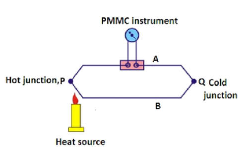
- When these junctions are kept at different temperatures, generally cold junction is kept at 0oC, and the measuring junction is kept at an unknown temperature which we want to measure (i.e. the temperature of the junction is raised by heating it). An e.m.f. will be generated in this circuit due to the temperature difference of the junctions.
- This e.m.f. is in the order of millivolts. And the e.m.f. can be measured with the help of a PMMC instrument by connecting it to the circuit as shown in Figure. When both the junctions are at the same temperature, e.m.f. generated at both junctions will be the same. No current will flow through the circuit. And there will be no deflection in the meter.
- When both junctions are at different temperatures, a current will flow through the meter. And the meter will show the deflection. As the generated. m.f. is proportional to the temperature difference, and the amount of current flow will also be proportional to the temperature difference. And therefore, the meter can be calibrated directly in terms of temperature.
- The reference or cold junction is normally connected to the measuring instrument and held at 0 C. For accurate temperature measurement, the reference junction temperature must remain constant or suitable compensation provided if it should change. To reduce inaccuracies, most thermocouples are now installed with instruments that provide automatic reference compensation.
Types of Thermocouple
- T – Type Thermocouple
Positive wire — Cu
Negative wire — Constantan
It can be used up to 350oC. It is very stable and inexpensive. Generally, it is
used for very low-temperature applications.
- E – Type Thermocouple
Positive wire — Chrome
Negative wire — Constantan
It can be used up to 850oC. It is a most sensitive thermocouple. It generates a
high output voltage.
- J – Type Thermocouple
Positive wire — Iron
Negative wire — Constantan
It can be used up to 1000 C. It is a very common type of thermocouple. Its
stability is high.
- K — Type Thermocouple
Positive wire — Chrome
Negative wire — Alumel
It can be used up to 1200oC. It is a widely used type of thermocouple. It is a
cheaper type as compared to other types.
- S – Type Thermocouple
Positive wire — Platinum 10% Rhodium
Negative wire — Platinum
It can be used up to 1400oC. It has very high precision thus used for very high
accuracy requirements.
- The current will flow from + ve marked lead to the – ve marked lead. In
thermocouples, negative lead is generally a red-colored wire. The color of
positive lead will be according to its type.