Introduction
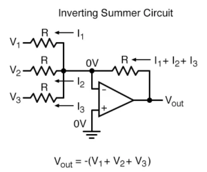
An R-2R Ladder Digital-to-Analog Converter (DAC) is a widely used DAC architecture that converts digital binary data into an equivalent analog output voltage using only two resistor values: R and 2R. The R-2R DAC is a variation of the inverting summing amplifier circuit.

Unlike the Binary Weighted DAC, which requires many different resistor values, the R-2R Ladder DAC uses only two resistor values, making it easier to design and manufacture. This DAC is commonly used in digital communication systems, audio devices, instrumentation, and embedded systems because of its simplicity, accuracy, and scalability.
Principle of R-2R Ladder DAC
The operation of an R-2R Ladder DAC is based on a resistive ladder network formed using resistors of values R and 2R. Each digital input bit controls a switch that connects either:
- Reference Voltage (VREF) for Logic 1
- Ground for Logic 0
The ladder network divides and combines the currents generated by each input bit. These currents are then summed by an operational amplifier to produce the corresponding analog output voltage.
3-Bit R-2R Ladder DAC
A 3-bit R-2R Ladder DAC consists of:
- Three digital input bits: B2, B1, and B0
- An R-2R resistor network
- An operational amplifier
- A reference voltage source
In a 3-bit DAC:
- B2 is the Most Significant Bit (MSB)
- B0 is the Least Significant Bit (LSB)
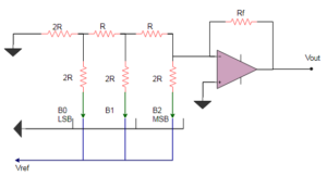
When a bit is HIGH (1), the corresponding switch connects the resistor branch to the reference voltage VREF. When the bit is LOW (0), the branch is connected to ground. The resistor ladder network combines the weighted contributions of all bits to generate an analog voltage proportional to the digital input.
Working of R-2R Ladder Network
The R-2R ladder network acts as a series of voltage dividers. Each successive bit contributes half the voltage contribution of the previous bit. As a result:
- MSB contributes the largest portion of the output voltage.
- LSB contributes the smallest portion of the output voltage.
The combined voltage generated by the ladder network is applied to the inverting input of an operational amplifier, which produces the final analog output.
Output Voltage Equation of R-2R DAC
The voltage produced by the resistor ladder network is:
:contentReference[oaicite:0]{index=0}
Where:
- VREF = Reference Voltage
- B = Binary Input Bits
- N = Number of Input Bits
The output voltage of the operational amplifier is:
:contentReference[oaicite:1]{index=1}
Substituting the ladder voltage expression:
:contentReference[oaicite:2]{index=2}
The gain of the DAC depends on the ratio Rf/R. For unity gain operation, a buffer amplifier can be used at the output stage.
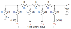
R-2R Resistive Ladder Network
The term “ladder” comes from the ladder-like arrangement of the resistors. The network consists of alternating R and 2R resistors connected in a series-parallel configuration. This arrangement offers several advantages:
- Only two resistor values are required.
- The output resistance remains constant.
- Design becomes simpler for higher-resolution DACs.
- Improved matching accuracy can be achieved.
Resolution of R-2R DAC
The resolution of an R-2R DAC depends on the number of input bits.
For an n-bit DAC:
:contentReference[oaicite:3]{index=3}
This value represents the smallest change in output voltage corresponding to a one-bit change in the digital input.
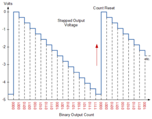
4-Bit R-2R DAC Operation
A 4-bit R-2R DAC has 16 possible input combinations ranging from:
- 0000 (Decimal 0)
- 1111 (Decimal 15)
As the binary count increases, the output voltage changes in equal steps, producing a staircase waveform.
The output can be used to:
- Control lamp brightness
- Control motor speed
- Generate analog signals
- Create waveform generators
Advantages of R-2R Ladder DAC
- Uses only two resistor values (R and 2R).
- Simple circuit design.
- Easy to fabricate using integrated circuits.
- High accuracy and good resistor matching.
- Output resistance remains constant regardless of the number of bits.
- Resolution can be increased without significantly affecting performance.
- Widely used in practical DAC implementations.
Disadvantages of R-2R Ladder DAC
- Conversion speed is relatively slow compared to some modern DAC architectures.
- Requires precise resistor matching for high accuracy.
- Switching errors can affect output performance.
Applications of R-2R Ladder DAC
- Audio Amplifiers
- Video Encoders
- Display Electronics
- Data Acquisition Systems
- Calibration Equipment
- Motor Control Systems
- Data Distribution Systems
- Digital Potentiometers
- Software-Defined Radio (SDR)
- Signal Generation Systems
Comparison Between Binary Weighted DAC and R-2R DAC
| Feature | Binary Weighted DAC | R-2R Ladder DAC |
|---|---|---|
| Resistor Values | Multiple Values Required | Only R and 2R Required |
| Design Complexity | Higher | Lower |
| Accuracy | Depends on Wide Resistor Range | Better Resistor Matching |
| Scalability | Difficult for Higher Bits | Easy for Higher Bits |
| Practical Usage | Limited | Widely Used |
Conclusion
The R-2R Ladder DAC is one of the most popular Digital-to-Analog Converter architectures because it uses only two resistor values, making it simple, accurate, and cost-effective. Its constant output resistance, ease of implementation, and scalability make it suitable for a wide range of applications, including audio systems, instrumentation, communication devices, and embedded systems.