- Line sensor detect the presence of a black line by emitting infrared (IR) light and detecting the light levels that return to the sensor.
Infrared (IR) Detection
- Infrared (IR) light is emitted by line sensor, which then measure the levels of reflected IR light to determine the presence of a black line. They accomplish this by utilizing a light sensor and an emitter (receiver).
- You can see an example TCRT5000 line sensor below. Your components may be laid out differently (all on one side, for example), but the components I will discuss will be present on most line sensors.
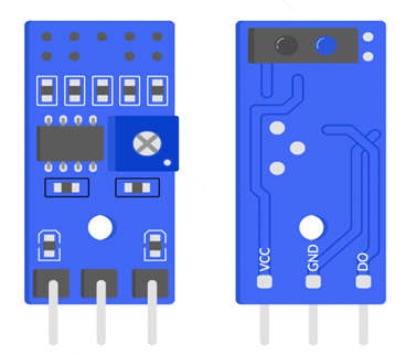
- Two round objects that resemble LEDs may be seen in the top right corner of the photograph. The IR emitter is the blue one, while the receiver is the black one. These devices additionally contain a potentiometer, which modifies the threshold of the device. This is accomplished by turning the white dial that resembles a cross on the left side of the image using a screwdriver.
- The apparatus will emit infrared light, and the sensor will measure the amount of light reflected from the ground beneath it. Some line sensors offer both analog and digital output. A continual reading of the light levels the sensor is sensing will be provided by the analog output, even though it is not constantly there. Before a Raspberry Pi can use an analog signal, it must first convert it to a digital signal. By adjusting the potentiometer, the light levels are compared to a threshold level, which produces the digital output. The digital output will be high if the sensor does not get enough light to go above the threshold value (1). If enough light is received and the threshold value is surpassed, the pin will be set to low (0).
- These devices’ configurations may appear a little disorganized at first, but it makes more sense if you realize that the sensor is intended to identify black lines. When a black surface is underneath, the output will be set to high (1) because a black line won’t reflect as much light.
How to use a Line Sensor
The line sensor also has an array of pins, some of which you will have to connect to the Raspberry Pi you are using.
- VCC needs to be connected to a voltage between 3.3 and 5V, to power the device.
- GND is the ground pin that is required to complete the circuit.
- AO is the analog output (this will not work with the Raspberry Pi).
- DO is the digital output pin (this will work with the Raspberry Pi).
- The VCC pin here can take a range of voltages, so potential dividers are not necessary. It is also worth noting that the AO pin does not feature on all line sensors.
Two sensors are better than one
- You can create a line-following robot with only one sensor, as this is enough to detect a line underneath the robot. If the robot strays from the line, though, it is very difficult to work out which way it needs to turn to find the line again.
- If the line is in the center of the robot, both sensors will return a 0 from their digital pins, as they are both over the white background.
- However, if the robot moves to the right, the left sensor will eventually cross onto the line, changing its output to a 1. When this happens, the robot should correct its course and turn left. Once the sensor returns to a 0 value, we know that the line is back in the middle of the robot.
- The same applies when the robot turns too far left; the right sensor will move over the line and change its reading. The robot should then turn right to the right to correct itself.
Features & Specifications of of TCRT5000 IR Sensor
The features and specifications of the TCRT5000 IR Sensor include the following.
- It is available in a leaded package.
- The type of detector used is photo-transistor.
- The Peak operating distance is 2.5 mm.
- Collector current ranges from 0.2 mm – 15 mm.
- The typical o/p current blow test (IC) is 1 mA.
- Blocking filter for daylight.
- The wavelength of the emitter is 950 nm.
- Infrared sensor including the o/p of transistor.
- The operating voltage is 5V.
- The forward current of the diode is 60mA.
- Output data is analog/digital.
- The Collector current of the transistor is 100mA.
- Operating temperature ranges from -25°C to +85°C.
- The equivalent TCRT5000 IR sensor is RPR220 and other infrared sensors are IR LED, IR Photodiode, qtr-1rC, GP2Y0A21, TSOP, etc.
Applications of TCRT5000 IR Sensor
The applications of the TCRT5000 IR sensor include the following.
- TCRT5000 IR sensor is used in IR sensor modules.
- It is used in the applications of proximity detection.
- Used in maze solver robots/ Line follower.
- Used in Obstacle avoidance/detection.
- This TCRT5000 IR sensor is used to verify the existence of a physical object like noticing a coil within a coin sorting machine.
- Used to detect the color on a white or black scale and this principle is used in line following the robot project. The dissimilar shades will modify the reflected IR light level.
- The TCRT5000 IR sensor is normally used to calculate the distance of the object or target.