
Introduction
A Doherty amplifier is a high-efficiency radio frequency (RF) power amplifier widely used in wireless communication systems. It is particularly useful in applications that require efficient amplification of signals with a high peak-to-average power ratio (PAPR), such as cellular base stations and modern wireless networks.
Unlike a conventional RF power amplifier, a Doherty amplifier uses two amplifier paths to improve power efficiency at different output power levels. This architecture helps maintain high efficiency when amplifying signals with varying power levels.

What Is a Doherty Amplifier?
The Doherty amplifier was invented by William H. Doherty at Bell Telephone Laboratories in 1936. It is a modified RF power amplifier architecture designed to improve efficiency, particularly when operating below peak output power. A conventional Class B amplifier can provide good efficiency at high output power, but its efficiency decreases when amplifying signals at lower power levels. The Doherty architecture addresses this limitation by combining two amplifiers that operate differently depending on the input signal level.
The two amplifier paths work together to deliver the required output power while improving overall power efficiency. This makes the Doherty amplifier suitable for transmitting modern communication signals with high peak-to-average power ratios.
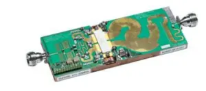
Typical Doherty RF amplifier demonstration board showing the basic RF circuit design
Doherty Amplifier Block Diagram
A basic Doherty amplifier consists of two main amplifier stages:
- Carrier Amplifier: Usually operates in Class AB mode and amplifies the input signal at low and moderate power levels.
- Peaking Amplifier: Usually operates in Class C mode in a conventional design and becomes active as the input signal power increases.
These amplifiers work together to improve the efficiency of the overall RF power amplification system.
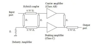
Block diagram of a simple Doherty amplifier
Working Principle of a Doherty Amplifier
The Doherty amplifier improves efficiency by controlling how the carrier and peaking amplifiers contribute to the output signal. Its operation can be understood through the following steps.
1. Input Signal Splitting
The input RF signal is divided into two paths using an input power splitter or an appropriate RF input network. These paths feed the carrier amplifier and the peaking amplifier. The required phase relationship between the two signals depends on the circuit topology and the design of the input and output networks.
2. Carrier Amplifier Operation
The carrier amplifier, typically a Class AB amplifier, operates over a wide range of input signal levels. At lower output power levels, it provides most or all of the amplified signal power. This arrangement helps the amplifier maintain good efficiency when the transmitted signal is below its maximum power level.
3. Peaking Amplifier Operation
As the input signal power increases, the peaking amplifier begins to conduct and contributes additional RF power to the output. The peaking amplifier helps the overall system handle higher signal peaks without requiring the carrier amplifier to operate inefficiently across the entire power range.
4. Impedance Transformation and Phase Alignment
A Doherty amplifier uses an impedance inverter, commonly implemented using a quarter-wave transmission line, to transform the effective load impedance seen by the carrier amplifier. As the peaking amplifier contributes more current, the load impedance presented to the carrier amplifier changes. This load modulation allows the carrier amplifier to maintain efficient operation over a wider range of output power levels. The input and output networks are designed to ensure that the amplified signals combine correctly at the output.
5. Combining the Amplified Signals
The carrier and peaking amplifier outputs combine to produce the final amplified RF signal. When properly designed, the Doherty architecture provides the required output power while improving efficiency at backed-off power levels. This makes it particularly useful for wireless transmitters that must handle signals with large variations between their average and peak power levels.
Advantages of a Doherty Amplifier
- High Power Efficiency: Improves efficiency, especially at output power levels below the maximum rated power.
- Suitable for High-PAPR Signals: Handles signals with significant variations in instantaneous power, which are common in modern wireless communication systems.
- Reduced Power Consumption: Improved RF efficiency can reduce the amount of DC power required for a given RF output power.
- Improved Thermal Performance: Lower power dissipation under suitable operating conditions can reduce cooling requirements.
- Practical RF Architecture: Provides an established approach to improving power amplifier efficiency without relying exclusively on techniques such as envelope tracking.
Disadvantages of a Doherty Amplifier
- Limited Bandwidth: Traditional quarter-wave impedance inverters and phase relationships can make wideband operation challenging.
- Higher Design Complexity: The carrier and peaking amplifiers must be carefully matched and coordinated to achieve optimum performance.
- Increased Cost: Using two amplifier paths and additional RF components can increase implementation costs compared with a single-amplifier design.
- Phase and Impedance Sensitivity: Variations in phase, impedance, and component characteristics can reduce efficiency and degrade signal quality.
- Complex Optimization: Achieving high efficiency, good linearity, and wide bandwidth simultaneously requires careful RF circuit design.
Applications of Doherty Amplifiers
Doherty amplifiers are widely used in applications where high RF power efficiency is important, including:
- Cellular base stations
- 4G LTE and 5G wireless communication systems
- RF transmitters
- Wireless broadband infrastructure
- Communication power amplifiers
- High-efficiency radio transmission systems
Conclusion
The Doherty amplifier is an important RF power amplifier architecture designed to improve efficiency when handling signals with varying power levels. By combining a carrier amplifier with a peaking amplifier and using impedance modulation, it achieves better efficiency at backed-off output power levels than many conventional amplifier designs. Although bandwidth limitations, design complexity, and implementation costs can present challenges, Doherty amplifiers remain a widely used solution in modern wireless communication systems, particularly in cellular base stations and high-efficiency RF transmitters.